Seamless Communication: Sending Messages Between ESP8266 Modules on a Shared Wi-Fi Network

Introduction

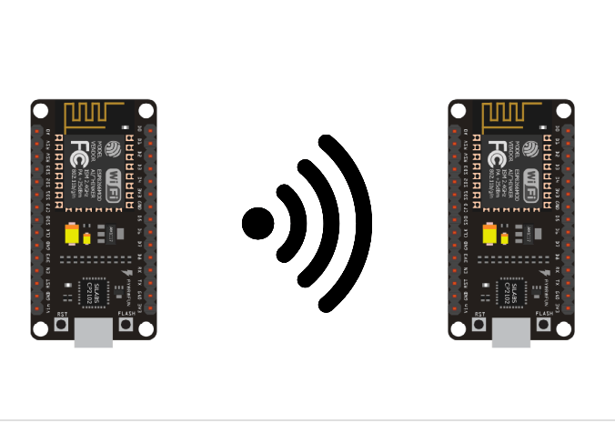
In the Internet of Things (IoT), seamless communication between devices is key to building smart systems. The ESP8266, a popular Wi-Fi module, allows easy wireless interaction between devices. In this project, we’ll demonstrate how to send and receive messages between two ESP8266 modules on the same Wi-Fi network by setting up one as a server and the other as a client. This simple setup forms the foundation for more complex IoT applications

Parts Required

  1. 2 x ESP8266 Modules (e.g., NodeMCU or ESP-01)
    • These will serve as the server and client for communication.
  2. USB to Micro-USB Cables
    • For powering and programming the ESP8266 modules.

Set Up One ESP8266 as a Server

The first ESP8266 will act as a server, listening for incoming connections from the client (the second ESP8266).

Server Code (ESP8266 A):

#include <ESP8266WiFi.h>

const char* ssid = “your_SSID”; // Replace with your Wi-Fi SSID
const char* password = “your_PASSWORD”; // Replace with your Wi-Fi password

WiFiServer server(80); // Server on port 80

void setup() {
Serial.begin(115200);
WiFi.begin(ssid, password);

while (WiFi.status() != WL_CONNECTED) {
delay(1000);
Serial.println(“Connecting to WiFi…”);
}

Serial.println(“Connected to WiFi”);
Serial.print(“IP Address: “);
Serial.println(WiFi.localIP());

server.begin(); // Start the server
Serial.println(“Server started”);
}

void loop() {
WiFiClient client = server.available(); // Check for incoming clients

if (client) {
Serial.println(“Client connected”);
while (client.connected()) {
if (client.available()) {
String message = client.readStringUntil(‘\n’); // Read incoming message
Serial.print(“Message received: “);
Serial.println(message);

// Respond to the client
client.println(“Hello from Server”);
}
}
client.stop();
Serial.println(“Client disconnected”);
}
}


2. Set Up the Second ESP8266 as a Client

The second ESP8266 will act as a client, connecting to the server and sending a “hi” message.

Client Code (ESP8266 B):

#include <ESP8266WiFi.h>

const char* ssid = “your_SSID”; // Replace with your Wi-Fi SSID
const char* password = “your_PASSWORD”; // Replace with your Wi-Fi password

const char* serverIP = “192.168.1.100”; // Replace with the server ESP8266’s IP address
const uint16_t serverPort = 80;

void setup() {
Serial.begin(115200);
WiFi.begin(ssid, password);

while (WiFi.status() != WL_CONNECTED) {
delay(1000);
Serial.println(“Connecting to WiFi…”);
}

Serial.println(“Connected to WiFi”);
}

void loop() {
WiFiClient client;

if (client.connect(serverIP, serverPort)) {
Serial.println(“Connected to server”);

// Send a “hi” message to the server
client.println(“hi”);
Serial.println(“Message sent: hi”);

while (client.connected()) {
if (client.available()) {
String response = client.readStringUntil(‘\n’); // Read server’s response
Serial.print(“Response received: “);
Serial.println(response);
}
}

client.stop();
Serial.println(“Disconnected from server”);
} else {
Serial.println(“Connection to server failed”);
}

delay(5000); // Wait 5 seconds before sending the next message
}

Github link :  https://github.com/makertribe/IoT-Codes/blob/86256d11a19cd864dcd9033f4bbbcf5ccf8dca91/Seamless%20Communication%3A%20Sending%20Messages%20Between%20ESP8266%20Modules%20on%20a%20Shared%20Wi-Fi%20Network


GAS Sensor with Arduino Uno

Introduction

Gas sensors play a crucial role in detecting hazardous gases in the environment. The MQ-2 sensor is widely used for its sensitivity to gases like LPG, propane, methane, hydrogen, and smoke. By connecting this sensor to an Arduino Uno, you can create a system that monitors gas levels and triggers alerts when necessary.

Parts Required

Before you start, ensure you have the following components:

  • MQ-2 Gas Sensor
  • Arduino Uno
  • Jumper Wires
  • LED
  • Bread Board

MQ-2 Gas Sensor Pinout

Understanding the pinout of the MQ-2 sensor is essential for making the right connections:

  • VCC: Connects to the 5V power supply of the Arduino.
  • GND: Connects to the ground (GND) on the Arduino.
  • AO (Analog Output): Outputs an analog signal proportional to the concentration of gas. Connect this to an analog input pin on the Arduino.
  • DO (Digital Output): Outputs a digital signal (high or low) when the gas concentration exceeds a certain threshold. This can be connected to a digital pin on the Arduino.
  • D11 : Connects to the input for the Positive pin of the Red LED
  • D12 : Connects to the positive pin of the  Green LED

CODE: 

int mq2Pin = A0;        // Analog pin connected to MQ-2 sensor
int redLEDPin = 13;     // Digital pin connected to Red LED
int greenLEDPin = 12;   // Digital pin connected to Green LED
int buzzerPin = 11;     // Digital pin connected to Buzzer
int threshold = 500;    // Threshold value for alcohol detection (adjust as needed)
void setup() {
  pinMode(redLEDPin, OUTPUT);   // Set the Red LED pin as output
  pinMode(greenLEDPin, OUTPUT); // Set the Green LED pin as output
  pinMode(buzzerPin, OUTPUT);   // Set the Buzzer pin as output
  Serial.begin(9600);           // Initialize serial communication
}
void loop() {
  int sensorValue = analogRead(mq2Pin);  // Read the analog value from the sensor
  Serial.print(“Sensor Value: “);        // Print the sensor value to the Serial Monitor
  Serial.println(sensorValue);
  // Compare the sensor value to the threshold
  if (sensorValue > threshold) {
    digitalWrite(redLEDPin, HIGH);   // Turn on the Red LED if alcohol is detected
    digitalWrite(greenLEDPin, LOW);  // Turn off the Green LED
    digitalWrite(buzzerPin, HIGH);   // Turn on the Buzzer
    Serial.println(“Alcohol Detected!”);  // Print message to Serial Monitor
  } else {
    digitalWrite(redLEDPin, LOW);    // Turn off the Red LED
    digitalWrite(greenLEDPin, HIGH); // Turn on the Green LED if no alcohol is detected
    digitalWrite(buzzerPin, LOW);    // Turn off the Buzzer
  }
  delay(1000);  // Wait for 1 second before the next reading
}
GITHUB link : https://github.com/makertribe/IoT-Codes/blob/9453e325a378052d0904ed1e72199af2e369fba3/MQ2%20Gas%20sensor%20connection%20with%20arduino
OUTPUT : 


IR Sensor with Arduino uno

Introduction :

An IR sensor is an electronic device that measures and detects infrared radiation in its environment. IR sensors are commonly used for object detection, distance measurement, and line following in robotics.

There are different types of IR sensors:

  • IR Transmitter and Receiver Pair: Used for object detection.
  • IR Proximity Sensor: Measures the distance to an object.
  • IR Reflective Sensor: Used in line-following robots.

Pin Connections:

  • VCC: Connect to 5V on the Arduino.
  • GND: Connect to GND on the Arduino.
  • OUT: Connect to a digital input pin on the Arduino (e.g., pin 2)


Code:

#define IR_PIN 2 // Pin connected to the IR sensor OUT pin

void setup() {
pinMode(IR_PIN, INPUT); // Set IR sensor pin as input
Serial.begin(9600); // Initialize serial communication for debugging
}

void loop() {
int irState = digitalRead(IR_PIN); // Read the state of the IR sensor

if (irState == LOW) {
// Object detected
Serial.println(“Object detected!”);
} else {
// No object detected
Serial.println(“No object.”);
}

delay(500); // Wait for 500 ms before checking again
}

https://github.com/makertribe/IoT-Codes/blob/68620130d0d5cb97e89ac367d857ce6abbf88895/IR%20sensor

Output :


PIR Sensor with Arduino uno

Introduction: 

A PIR (Passive Infrared) sensor like the HW-416 is typically used to detect motion by sensing changes in infrared radiation in its surroundings. These sensors are widely used in security systems, automatic lighting, and similar applications where detecting human presence or movement is required

Key Features of PIR Sensors:

  • Motion Detection: Detects changes in infrared radiation caused by moving objects, particularly humans and animals.
  • Digital Output: Provides a HIGH signal when motion is detected and a LOW signal otherwise.
  • Adjustable Sensitivity and Time: Some sensors allow adjustments to the sensitivity (detection range) and the duration for which the output remains HIGH after detecting motion.

Pin Connections:

  • VCC: Connect to 5V on the Arduino.
  • GND: Connect to GND on the Arduino.
  • OUT: Connect to a digital input pin on the Arduino (e.g., pin 2).

Code:

#define PIR_PIN 2        // Pin connected to PIR sensor OUT pin
#define LED_PIN 13       // Pin connected to an LED for visual indication
void setup() {
  pinMode(PIR_PIN, INPUT);  // Set PIR pin as input
  pinMode(LED_PIN, OUTPUT); // Set LED pin as output
  Serial.begin(9600);       // Start serial communication for debugging
}
void loop() {
  int pirState = digitalRead(PIR_PIN);  // Read PIR sensor state
  if (pirState == HIGH) {
    // Motion detected
    Serial.println(“Motion detected!”);
    digitalWrite(LED_PIN, HIGH);  // Turn on the LED
  } else {
    // No motion
    Serial.println(“No motion.”);
    digitalWrite(LED_PIN, LOW);   // Turn off the LED
  }
  delay(1000);  // Wait for 1 second before checking again
}
https://github.com/makertribe/IoT-Codes/blob/51eb3e61145189586acfb33bbf6545d8c6f15267/PIR%20sensor

Output:


RFID sensor with Arduino uno

Introduction : 

An RFID (Radio Frequency Identification) sensor is a device used to identify and track tags attached to objects wirelessly. RFID systems are composed of two main components: the RFID reader (or sensor) and the RFID tag. The RFID reader emits radio waves that power the RFID tag, which then responds by transmitting its unique identification data back to the reader.

Key Components

  1. RFID Reader: The reader (or sensor) sends out radio waves to detect and communicate with RFID tags. One of the most commonly used RFID reader modules in DIY projects is the RFID-RC522.
  2. RFID Tag: A small chip with an antenna that stores a unique ID. There are different types of tags, such as passive (which do not have a power source and rely on the reader’s signal) and active (which have their own power source).

How RFID Works

  1. Communication: The RFID reader emits radio waves in a specific frequency range (typically 13.56 MHz for the MFRC522). When an RFID tag enters this range, the radio waves power the tag’s chip.
  2. Data Transmission: The powered tag transmits its stored data (usually a unique identifier) back to the reader via modulated radio waves.
  3. Processing: The RFID reader decodes this information and sends it to a microcontroller (like an Arduino) or a computer for further processing.

RFID Reader: MFRC522

The MFRC522 is a popular RFID reader module used in Arduino projects. It operates at a frequency of 13.56 MHz and is capable of reading and writing data to RFID tags.

Features:

  • Operating Voltage: 3.3V
  • Frequency: 13.56 MHz
  • Communication Protocol: SPI (Serial Peripheral Interface)
  • Range: Typically 0-5 cm depending on the tag and environment

Connecting  the MFRC522 to an Arduino Uno

Here’s how you would connect the MFRC522 module to an Arduino Uno:

  1. VCC: Connect to the 3.3V pin on the Arduino (do not connect to 5V as it might damage the module).
  2. GND: Connect to the GND pin on the Arduino.
  3. RST: Connect to digital pin 9 on the Arduino.
  4. SDA/SS: Connect to digital pin 10 on the Arduino (Slave Select).
  5. MOSI: Connect to digital pin 11 on the Arduino (Master Out Slave In).
  6. MISO: Connect to digital pin 12 on the Arduino (Master In Slave Out).
  7. SCK: Connect to digital pin 13 on the Arduino (Serial Clock)
Version 1.0.0

CODE:

#include <SPI.h>
#include <MFRC522.h>
#define SS_PIN 10
#define RST_PIN 9
#define GREEN_LED_PIN 6  // Pin for green LED
#define RED_LED_PIN 7    // Pin for red LED
MFRC522 mfrc522(SS_PIN, RST_PIN);  // Create MFRC522 instance
void setup() {
  Serial.begin(9600);  // Initialize serial communications at 9600 baud
  SPI.begin();         // Init SPI bus
  mfrc522.PCD_Init();  // Init MFRC522
  pinMode(GREEN_LED_PIN, OUTPUT);  // Set the green LED pin as an output
  pinMode(RED_LED_PIN, OUTPUT);    // Set the red LED pin as an output
  Serial.println(“Access Control System Ready. Scan your RFID tag…”);
}
void loop() {
  // Turn off both LEDs initially
  digitalWrite(GREEN_LED_PIN, LOW);
  digitalWrite(RED_LED_PIN, LOW);
  // Look for new cards
  if (!mfrc522.PICC_IsNewCardPresent()) {
    return;
  }
  // Try to select one of the cards
  if (!mfrc522.PICC_ReadCardSerial()) {
    // If the card fails to read, light up the red LED and display a failure message
    Serial.println(“Failed to read card!”);
    digitalWrite(RED_LED_PIN, HIGH);  // Turn on the red LED
    delay(2000);  // Keep the red LED on for 2 seconds
    digitalWrite(RED_LED_PIN, LOW);  // Turn off the red LED
    return;
  }
  // If the card is successfully read, light up the green LED
  Serial.print(“UID tag: “);
  for (byte i = 0; i < mfrc522.uid.size; i++) {
    Serial.print(mfrc522.uid.uidByte[i] < 0x10 ? ” 0″ : ” “);
    Serial.print(mfrc522.uid.uidByte[i], HEX);
  }
  Serial.println();
  Serial.println(“Card successfully read!”);
  digitalWrite(GREEN_LED_PIN, HIGH);  // Turn on the green LED
  delay(2000);  // Keep the green LED on for 2 seconds
  digitalWrite(GREEN_LED_PIN, LOW);  // Turn off the green LED
  mfrc522.PICC_HaltA();  // Halt PICC
}
https://github.com/makertribe/IoT-Codes/blob/79fc6292652a20f620da79fbfb83ae60d937a128/RFID%20sensor
Library  install : 

Install the Servo Library (if not already installed):

  • Open the Arduino IDE.
  • Go to Sketch > Include Library > MFRC522.

OUTPUT:


Soil Moisture sensor using ARDUINO UNO

Introduction : 

A soil moisture sensor is a device that measures the volumetric water content in soil. It is commonly used in gardening, agriculture, and environmental monitoring to keep track of soil moisture levels and automate watering systems.


Key Features

  • Operating Voltage: 3.3V to 5V
  • Output: Analog voltage (typically 0-1023 on the Arduino’s ADC)
  • Probe Type: Two-prong (for resistive measurement)

Components

  • Soil Moisture Sensor Module: Usually consists of two main parts: the sensor probe and the signal conditioning circuit.
  • Sensor Probe: Two metal prongs that are inserted into the soil.
  • Signal Conditioning Circuit: Converts the resistance between the probes to a voltage output.

Wiring the Soil Moisture Sensor to Arduino

  1. VCC (Sensor) to 5V (Arduino)
  2. GND (Sensor) to GND (Arduino)
  3. A0 (Sensor) to an analog input pin (e.g., A0) on the Arduino


CODE: 

const int sensorPin = A0; // Pin connected to the analog output of the sensor
const int relayPin = 7; // Pin connected to the relay module or LED
int sensorValue = 0; // Variable to store the value coming from the sensor

void setup() {
Serial.begin(9600); // Initialize serial communication at 9600 baud
pinMode(relayPin, OUTPUT); // Set the relay pin as an output
digitalWrite(relayPin, HIGH); // Ensure the relay is off initially (active LOW)
}

void loop() {
sensorValue = analogRead(sensorPin); // Read the analog value from the sensor

Serial.print(“Soil Moisture: “);
Serial.println(sensorValue); // Print the value to the Serial Monitor

if (sensorValue > 600) { // If the soil is dry (adjust threshold as needed)
digitalWrite(relayPin, LOW); // Turn on the relay (or LED)
} else {
digitalWrite(relayPin, HIGH); // Turn off the relay (or LED)
}

delay(1000); // Wait for 1 second before taking another reading
}

https://github.com/makertribe/IoT-Codes/blob/bd52674376b39d6ba31d668bebdd77deacbc42a3/Soil%20Moisture%20with%20UNO

Output : 

SG90 Servo Motor with ARDUINO UNO

Introduction :

The SG90 is a popular micro servo motor commonly used in robotics and DIY electronics projects due to its compact size, lightweight, and affordability.


Key Features

  • Operating Voltage: 4.8V to 6V
  • Stall Torque: 1.8 kg·cm at 4.8V
  • Operating Speed: 0.1 sec/60° at 4.8V
  • Rotation Range: 0 to 180 degrees
  • Control Signal: PWM (Pulse Width Modulation)
  • Dimensions: 22.2 x 11.8 x 31 mm
  • Weight: 9 grams

Pin Configuration

  1. Orange/Yellow Wire: Signal (PWM input)
  2. Red Wire: VCC (Power supply, 4.8V to 6V)
  3. Brown/Black Wire: GND (Ground)


CODE :

#include <Servo.h>
Servo myServo;  // Create a servo object to control the servo
const int servoPin = 9;  // Pin connected to the signal pin of the servo
void setup() {
  myServo.attach(servoPin);  // Attach the servo to the specified pin
}
void loop() {
  // Move the servo to 0 degrees
  myServo.write(0);
  delay(1000);  // Wait for 1 second
  // Move the servo to 90 degrees
  myServo.write(90);
  delay(1000);  // Wait for 1 second
  // Move the servo to 180 degrees
  myServo.write(180);
  delay(1000);  // Wait for 1 second
  // Move back to 90 degrees
  myServo.write(90);
  delay(1000);  // Wait for 1 second
}
https://github.com/makertribe/IoT-Codes/tree/69696eb1ee7cc3caa9cfc90ed1d9622c10fd10a1
Library  install : 

Install the Servo Library (if not already installed):

  • Open the Arduino IDE.
  • Go to Sketch > Include Library > Servo.

Output:


Ultrasound Sensor HC-SR04 with ARDUINO UNO

Introduction : 

The HC-SR04 is an affordable and popular ultrasonic distance sensor widely used in robotics and various automation projects. It measures the distance to an object by using ultrasonic sound waves

Key Features

  • Operating Voltage: 5V DC
  • Quiescent Current: <2mA
  • Operating Current: 15mA
  • Measuring Range: 2 cm to 400 cm
  • Resolution: 0.3 cm
  • Frequency: 40 kHz
  • Dimensions: 45mm x 20mm x 15mm

Pin Configuration

  1. VCC: Power supply (5V)
  2. Trig: Trigger input
  3. Echo: Echo output
  4. GND: Ground


Code : 


const int trigPin = 9; // Trigger pin
const int echoPin = 10; // Echo pin

long duration;
float distanceCm;

void setup() {
Serial.begin(9600); // Initialize serial communication at 9600 baud
pinMode(trigPin, OUTPUT); // Set the trigPin as an OUTPUT
pinMode(echoPin, INPUT); // Set the echoPin as an INPUT
}

void loop() {
// Clear the trigPin by setting it LOW
digitalWrite(trigPin, LOW);
delayMicroseconds(2);

// Set the trigPin HIGH for 10 microseconds
digitalWrite(trigPin, HIGH);
delayMicroseconds(10);
digitalWrite(trigPin, LOW);

// Read the echoPin, returns the sound wave travel time in microseconds
duration = pulseIn(echoPin, HIGH);

// Calculate the distance
distanceCm = duration * 0.034 / 2;

// Print the distance to the Serial Monitor
Serial.print(“Distance: “);
Serial.print(distanceCm);
Serial.println(” cm”);

delay(1000); // Wait for 1 second before taking the next measurement
}


https://github.com/makertribe/IoT-Codes/blob/2a7e8645891fba590b21c8a1b9db02ee2c0192ae/Ultrasoundsensor


Output :


Temperature Sensor using ARDUINO UNO

Introduction : 

The DHT11 is a basic, low-cost digital temperature and humidity sensor. It uses a capacitive humidity sensor and a thermistor to measure the surrounding air, and it outputs a digital signal on the data pin (no analog input pins needed)

Key Features

  • Temperature Range: 0 to 50°C (±2°C accuracy)
  • Humidity Range: 20% to 90% RH (±5% accuracy)
  • Operating Voltage: 3.5V to 5.5V
  • Max Current: 2.5mA (during conversion)
  • Output: Digital signal via single-bus interface

Pin Configuration

  1. VCC: Power supply (3.5V to 5.5V)
  2. Data: Serial data output (connect to a digital pin on the microcontroller)
  3. GND: Ground


Connection:

  • VCC to 5V (Arduino)
  • GND to GND (Arduino)
  • Data to a digital pin (e.g., pin 4) on the Arduino


Code : 

#include <DHT.h>
#define DHTPIN 4       // Pin connected to the Data pin of DHT11
#define DHTTYPE DHT11  // DHT 11 sensor type
DHT dht(DHTPIN, DHTTYPE);
void setup() {
  Serial.begin(9600);  // Initialize serial communication at 9600 baud
  dht.begin();         // Initialize the DHT sensor
}
void loop() {
  delay(2000);         // Wait a few seconds between measurements
  float humidity = dht.readHumidity();         // Read humidity
  float temperatureC = dht.readTemperature();  // Read temperature as Celsius
  float temperatureF = dht.readTemperature(true); // Read temperature as Fahrenheit
  // Check if any reads failed and exit early (to try again).
  if (isnan(humidity) || isnan(temperatureC) || isnan(temperatureF)) {
    Serial.println(“Failed to read from DHT sensor!”);
    return;
  }
  Serial.print(“Humidity: “);
  Serial.print(humidity);
  Serial.print(” %\t”);
  Serial.print(“Temperature: “);
  Serial.print(temperatureC);
  Serial.print(” *C “);
  Serial.print(temperatureF);
  Serial.println(” *F”);
}
https://github.com/makertribe/IoT-Codes/blob/8827f3514542eaead0f456b647918363b2247cc6/temperature%20sensor%20code
DHT-sensor-library-master
Output: 


Basic LED blinking using Arduino UNO

Introduction :

The Arduino UNO is perfect for beginners. A common first project is making an LED blink, introducing you to Arduino programming and hardware. Let’s light up your path into electronics with this simple first experiment


Hardware needed :

  1. Arduino UNO (with cable)
  2. LED light 

Connection : 

  1. Connect your laptop and UNO board using the UNO cable
  2. Open a blank IDE and configure your UNO to the IDE
  3. Connect the Longer pin of the LED to the digital pin 13
  4. The shorter end of the led to the GND present next to  pin13Arduino UNO R3 SMD Atmega328P – Indian Hobby Center

Connection diagram : 


Bad Tutorial? Connect an LED directly to pin 13 without resistor? - Website and Forum - Arduino Forum

CODE : 

void setup() {                         //Initialization
  pinMode(13, OUTPUT);  // change pin accordingly
}
void loop(){                                   // working loop
  digitalWrite(13,HIGH);          // High = On
  delay(1000);
  digitalWrite(13,LOW);          // Low = OFF
  delay(1000);
}
https://github.com/makertribe/IoT-Codes/blob/18b94243947e4dfaa5d09eb944850c69dfd53a4c/LED%20blinking%20in%20UNO%20board
OUTPUT :